Table of Contents
Agents
Diese Seite ist auf deutsch verfügbar.
 The Agent is what the player interacts with on the playing field. It is a Java software which runs on a Raspberry Pi computer1). Connected to that Pi is a breakout board (see upper right corner) where You connect the In- and Output devices to.
The input device is currently only one single push button2). The use of this button is reported to the commander by two subsequent events. First when it is pushed down and second when it is released.
The output devices are
- 5x colored lights in the following order: white, red, yellow, green, blue. The lights are usually 12 Volt LED strips.
- 3x sirens with different signals. These sirens are connected via a relay.
- 1x 12 Volt buzzer for close range notifications.
- 1x LCD with 20 cols x 4 rows
All those devices are optional. Meaning, that an Agent doesn't have to support them all. In fact we didn’t build any agent in the past, that had a full device set. We have agents for special purposes.
A siren agent is just a box with three sirens and big fat battery to power them. We put it somewhere on the field. Nobody needs to get too close to it. So a button is also not needed on the sirens.
A capture point has lights, a buzzer and a button. As it is usually positioned directly in the center of the action, it needs to be robust and water/paint proof. On the right side You see an example for this agent type. It has been build into a DN75 PVC drainpipe with a length of 1 meter.
Spawn agents (as seen on the middle right) are located in the player spawn. They have a LCD to inform the teams about current events, scores, times etc. The have a button to signal a player respawn, lights and a buzzer.
The purpose of the RLGS (Real Life Gaming System) is to realize games for tactical sports like paintball, airsoft, Nerf or Laser Tag. RLGS adapts well known multiplayer modes from games like Battlefield, Call of Duty, FarCry, Planetside 2 oder Counterstrike to be played in real life.
The RLGS concept consists of two basic elements: the commander and one or more agents (this project).
Agents can produce optical and acoustical signals and detect events (currently only the press of a button). They do not know anything about why they are flashing LEDs, sounding sirens or why somebody presses their buttons. They completely rely on the commander to tell them what to do. The commander is the only one who keeps track about the game situation.
The concept of an agent contains the following in- and output devices.
- 5 light signals, colored in “white, red, yelllow, green, blue”
- 3 Sirens
- a buzzer for local player feedback
- 2 Buttons for player interaction
- and a 20×4 Textdisplay
An agent does not have to be fully equipped with every device possible. Such an complete system, should not be necessary. Nevertheless, the software understands all signals, even if the addressed device is not connected. In this case the signal is accepted but ignored.
Software
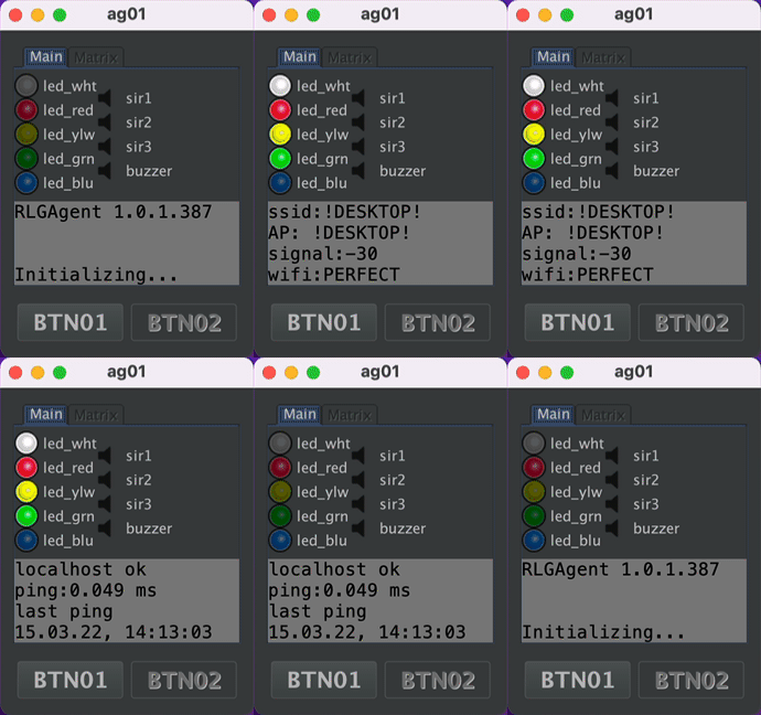 When the software is running on a normal desktop pc, the hardware is simulated in a window. This is very helpful to try out new game modes during development or for You to get a feeling for the whole system. There is a prepared virtual machine that lets You try out the whole system on Your own pc without complicated installation or configuration.
Hardware
PCB
There is a breakout board to easily connect a Raspberry Pi computer to the external hardware. You can get Your own PCB from any pcb manufacturing service, that accepts a ( Gerber file). Of course You can directly order the PCB from JLCPCB, like we did. Ein sog. Breakout Board, dass Ihr euch direkt bei einem beliebigen Platinen Dienst fertigen lassen könnt oder direkt bei JLCPCB.
List of electronic parts
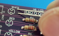
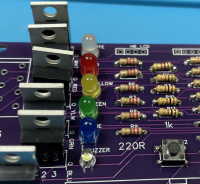
- 6x LEDs colored: white (2x), red, yellow, green, blue. the longer pin of the led inserted on the upper side.
- 6x IRLZ34 N-Channel MOSFET the metal cooler is facing to the upper side
- 6x 220 Ω resistors
- 5x 1 kΩ resistors
- 8x 10 kΩ resistors
- (optional) WAGO connectors 10pin and 8pin - see list of materials above. When used, the connectors are facing to the outside - away from the PCB.
- 2x 6x6mm microbuttons. The metal contacts are on the left and right side.
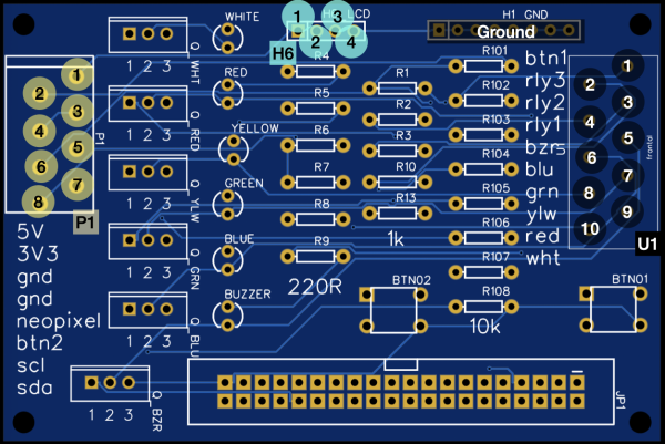
Boarddescription
| Block | Pin | Belegung/Usage |
|---|---|---|
| U1 | 1 | Button 1 |
| 2 | Signal Line for Relay 3 → Siren 3 | |
| 3 | Signal Line for Relay 2 → Siren 2 | |
| 4 | Signal Line for Relay 1 → Siren 1 | |
| 5 | GND Return-Line for 12 Volts Buzzer | |
| 6 | GND Return-Line for 12 Volts, LED blue | |
| 7 | GND Return-Line for 12 Volts, LED green | |
| 8 | GND Return-Line for 12 Volts, LED yellow | |
| 9 | GND Return-Line for 12 Volts, LED red | |
| 10 | GND Return-Line for 12 Volts, LED white | |
| H1 | all | Ground |
| H6 | 1 | 5 Volt |
| 2 | I2C Data SDA | |
| 3 | I2C Clock SCL | |
| 4 | Ground | |
| P1 | 1 | 5 Volts |
| 2 | 3,3 Volts | |
| 3 | Ground | |
| 4 | Ground | |
| 5 | Neopixel unused | |
| 6 | Button 2 unused | |
| 7 | I2C Clock SCL | |
| 8 | I2C Data SDA |
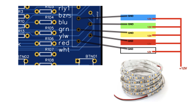 The LEDs on the pcb are control lights for the stripes that are attached later.
12V LED-Stripes
LED Stripes always have 2 wires connected (12 Volt and ground). We connect the 12V line directly to the PLUS of the battery. The ground lines are connected to the corresponding pin at the U1 block, Pin #6 - #9.
12V Buzzer
The connection of the buzzer is the same as with the LEDs. Connect the 12V line directly to the PLUS of the battery. The ground return-line goes to pin 5 at U1 block.
