Agents
Diese Seite ist auf deutsch verfügbar.
Agents are the gadgets on the field which players can hear, see and touch. Inside the agent is a small computer1) running an operating software2). An agent has different purposes and is designed to meet this task. Some agents are build to be a capture point. They must not break, just because they took some lines of paint or BBs. Some agents are kept in the spawn area. They have a display and maybe some sound output to inform the teams about the game situations. Sometimes we need only a siren somewhere on the field which nobody interacts with directly.
The output devices are
- 5x colored lights in the following order: white, red, yellow, green, blue. The lights are usually 12 Volt LED strips.
- 4x sirens with different signals. These sirens are connected via a relay. Depending on the relay's trigger level (high or low) you will have to apply a pull up oder pull down resistor. In future versions of the PCB these resistors will be provided on the board.
- 1x 12 Volt buzzer for close range notifications.
- 1x LCD with 20 cols x 4 rows
- 1 pushbutton for player interaction. In fact there is also a second button on the breakout board, but we don't use it, yet.
All those devices are optional. An agent doesn't have to support all of them. In fact we haven't yet build any agent, that had a full device set. A complete system, should not be necessary. However, the software understands all signals, even if the addressed devices are not connected. In this case the signal is accepted but ignored.
Agents do not know anything about why they are flashing LEDs, sounding sirens or why somebody presses their buttons. They completely rely on the commander to tell them what to do. The commander is the only one who keeps track about the game situation.
Hardware
The agent software is supposed to be run on a Raspberry Pi computer when used on the playing field. See Software section below.
PCB
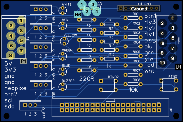
There is a breakout board to easily connect a Raspberry Pi computer to the external hardware. You can get Your own PCB from any pcb manufacturing service, that accepts a ( Gerber file). Of course You can directly order the PCB from JLCPCB, like we did. Ein sog. Breakout Board, dass Ihr euch direkt bei einem beliebigen Platinen Dienst fertigen lassen könnt oder direkt bei JLCPCB.
List of electronic parts
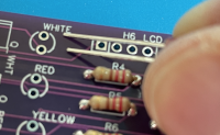
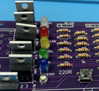
- 6x LEDs colored: white (2x), red, yellow, green, blue. the longer pin of the led inserted on the upper side.
- 6x IRLZ34 N-Channel MOSFET the metal cooler is facing to the upper side
- 6x 220 Ω resistors
- 5x 1 kΩ resistors
- 8x 10 kΩ resistors
- (optional) WAGO connectors 10pin and 8pin - see list of materials above. When used, the connectors are facing to the outside - away from the PCB.
- 2x 6x6mm microbuttons. The metal contacts are on the left and right side.
Boarddescription
| Block | Pin | Belegung/Usage |
|---|---|---|
| U1 | 1 | Button 1 |
| 2 | Signal Line for Relay 3 → Siren 3 | |
| 3 | Signal Line for Relay 2 → Siren 2 | |
| 4 | Signal Line for Relay 1 → Siren 1 | |
| 5 | GND Return-Line for 12 Volts Buzzer | |
| 6 | GND Return-Line for 12 Volts, LED blue | |
| 7 | GND Return-Line for 12 Volts, LED green | |
| 8 | GND Return-Line for 12 Volts, LED yellow | |
| 9 | GND Return-Line for 12 Volts, LED red | |
| 10 | GND Return-Line for 12 Volts, LED white | |
| H1 | all | Ground |
| H6 | 1 | 5 Volt |
| 2 | I2C Data SDA | |
| 3 | I2C Clock SCL | |
| 4 | Ground | |
| P1 | 1 | 5 Volts |
| 2 | 3,3 Volts | |
| 3 | Ground | |
| 4 | Ground | |
| 5 | Neopixel unused | |
| 6 | Button 2 unused | |
| 7 | I2C Clock SCL | |
| 8 | I2C Data SDA |
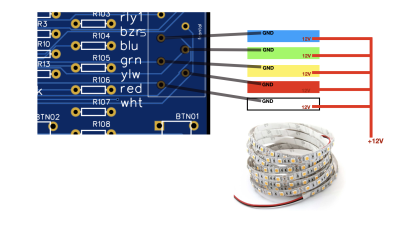 The LEDs on the pcb are control lights for the stripes that are attached later.
12V LED-Stripes
LED Stripes always have 2 wires connected (12 Volt and ground). We connect the 12V line directly to the PLUS of the battery. The ground lines are connected to the corresponding pin at the U1 block, Pin #6 - #9.
12V Buzzer
The connection of the buzzer is the same as with the LEDs. Connect the 12V line directly to the PLUS of the battery. The ground return-line goes to pin 5 at U1 block.
Software
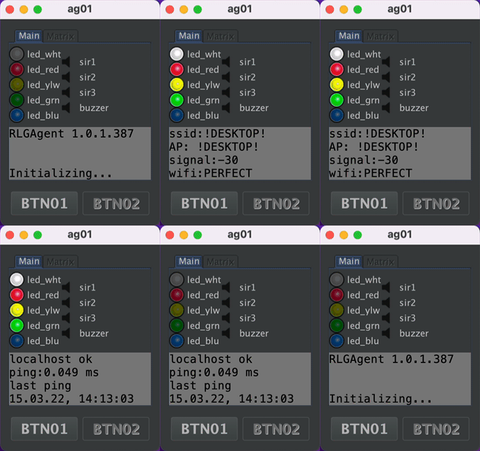 The Software realizes when it is run on a normal desktop computer. In this case, the hardware is simulated in a window. This is very helpful to try out new game modes during development. It may also be handy for You to get a feeling for the whole system.
There is a RLGS simulator, which is a prepared virtual machine with everything set up and pre installed properly.
Agents are supposed to run on Raspberry Pi computers with several input and output devices connected to them. Like LED stripes, sirens (switched by relay boards), push buttons, LCDs etc. But it is also possible to run them on a standard desktop computers (Mac, Windows, Linux). In this case, they start up a Swing GUI to simulate the aforementioned devices on the screen or via the sound card.
We use the Pi4J framework to connect the hardware to our Java source code. The whole framework is about to change drastically with the version 2. But for now we stick to Version 1, which still relies on the now deprecated WiringPi project, as it runs very well. Please note, that the Pin numbering used in the config files are named according to the WiringPi scheme.
WiringPi is not available in Raspbian anymore or as sourcecode. Until we are moving on to pi4j 2.0 (which based on pigpio), we stick with a source code mirror for WiringPi on GitHub, which works for us.
Usage
not yet…
Installation
The agent is written in Java and therefor available on nearly any platform. There are ready-made packages for Windows, Mac, Linux and Raspbian. The Raspbian version is only available as a service or demonized version. Linux versions are distributed via a package repository at flashheart.de. Refer to the download page for more information.
Workspace
The agent creates a workspace folder (if missing). The folder's location has to be specified via a -D argument on the java command line.
java -Dworkspace=/home/pi/rlgagent -jar /opt/rlgagent/rlgagent.jar
The standard installation packages contain this setting in the rlgagent.vmoptions file located in the installation folder.
- PC Linux as desktop application:
/opt/rlgagent - Raspian or Linux as a service/demon:
/opt/rlagentd - Mac:
/Applications/rlgagent - Windows:
%PROGRAMFILES%\rlgagent
The workspace folder contains
- the
config.txtfile - see Configs - a folder for log files. The agent archives a log file from a previous day on startup. The current day's or most recent file is always named
rlgagent.log - the mqtt persistence directory (technical stuff - ignore it)
- (optional) an audio folder for voices and intro songs
The structure looks like this:
rlgagent
|--rlgagent-385d8f4a-a0b7-496a-b3ca-7fe0f1cf20a0-tcplocalhost1883
| |--.lck
|--config.txt
|--audio
| |--announce
| | |--overtime.mp3
| | |--welcome.mp3
| | |--firstblood.mp3
| |--intro
| | |--future1.mp3
| | |--insomnia.mp3
| | |--feuerfrei.mp3
| | |--future2.mp3
| | |--bf3.mp3
| | |--eminem.mp3
| | |--sirius.mp3
| | |--metallica.mp3
| | |--nodyahead.mp3
| | |--thunder.mp3
| | |--killbill.mp3
|--logs
| |--rlgagent.log
| |--2022-06-21.rlgagent.log.gz
| |--2022-06-29.rlgagent.log.gz
| |--2022-06-27.rlgagent.log.gz
| |--2022-07-01.rlgagent.log.gz
config.txt
This is a standard Java properties file. If missing, it will be created with default values.
# Settings rlgagent
# the Raspi GPIO pin for the corresponding devices (Wiring Pi numbering scheme). Default sets the assignment
# to the standard agent [[https://easyeda.com/tloehr/rlg-mainboard-v11_copy|PCB]].
btn01=GPIO 3
btn02=GPIO 4
buzzer=GPIO 26
led_blu=GPIO 22
led_grn=GPIO 21
led_red=GPIO 1
led_wht=GPIO 2
led_ylw=GPIO 5
sir1=GPIO 7
sir2=GPIO 0
sir3=GPIO 6
sir4=GPIO 23
# Sets the debounce delay interval (in milliseconds) for all pin states.
# prevents //nervous buttons// from sending too many signals. increase if necessary.
button_debounce=200
# dimensions for the LCD.
lcd_cols=20
lcd_rows=4
# address on the i2c bus for the connected LCD
lcd_i2c_address=0x27
# the verbosity of the log file. possible values: OFF, DEBUG, TRACE, INFO, ERROR, WARN
loglevel=TRACE
# if a MCP23017 port extender is used, this is the address to find it on the i2c bus
mcp23017_i2c_address=0x20
# the [[http://mpg321.sourceforge.net/|mpg321] has to be installed on the agent, if we want
# to play sound files (useful for countdown voices or announcements). this is the path to the executable
mpg321_bin=/usr/local/bin/mpg321
# if options are needed (especially on the raspi) there can be added here
mpg321_options=
# the ordered list of mqtt brokers to search for. The agent tries to connect to the entries in this list
# - one by one. If the connection breaks during the game, the agent keeps trying to reconnect again.
mqtt_broker=mqtt mqtta mqttb
# settings for paho client
# https://www.eclipse.org/paho/files/javadoc/org/eclipse/paho/client/mqttv3/MqttConnectOptions.html#setCleanSession-boolean-
mqtt_clean_session=true
# the maximum number of messages in transit and not yet delivered.
mqtt_max_inflight=1000
# port address for the broker
mqtt_port=1883
# to be used for the event messages sent by this agent from 0 to 2. Where 0 is at most once, 1 at least once, 2 exactly once.
# https://en.wikipedia.org/wiki/MQTT#Quality_of_service|quality of service
mqtt_qos=2
# settings for paho client
# https://www.eclipse.org/paho/files/javadoc/org/eclipse/paho/client/mqttv3/MqttConnectOptions.html#setAutomaticReconnect-boolean-
mqtt_reconnect=true
# sets whether the event messages from this agent should be
# https://www.hivemq.com/blog/mqtt-essentials-part-8-retained-messages/
mqtt_retained=true
# the root element of the message topics to subscribe and send to. Keep the defaults.
mqtt_root=rlg
# settings for paho client
# https://www.eclipse.org/paho/files/javadoc/org/eclipse/paho/client/mqttv3/MqttConnectOptions.html#setConnectionTimeout-int-
mqtt_timeout=10
# the mqtt name of the agent by which it will be adressed within the network
# not to be confused with the DNS name. doens't have to be the same.
myid=ag01
# set if the attached siren relais trigger on low or high
trigger_on_high_sir1=true
trigger_on_high_sir2=true
trigger_on_high_sir3=true
trigger_on_high_sir4=true
# a random but unique id which is used to connect to the broker.
uuid=7823554b-b4b1-481d-ba2c-4f73f888efb
# only for Raspberry Pis. command line to be execute every 5 seconds. The results are parsed and sent to the commander via a status event message.
wifi_cmd=iwconfig wlan1
Messaging
The commander and the agents communicate via a MQTT broker.
Every agent has it's own channels:
- inbound command channel:
/<mqtt_root>/cmd/<myid>/#agent listens to what the commander wants him to do - outbound event channel:
/<mqtt_root>/evt/<myid>/#agent sends notifications about events that happened to him (e.G. button presses)
Inbound command channel
Every command has a subchannel on the inbound channel. E.G. signals to ag01 are sent to /rlg/cmd/ag01/signals, LCD content to /rlg/cmd/ag01/paged etc. The examples below are written with these default settings in mind.
Paged Displays
Topic: /rlg/cmd/<myid>/paged
Agents can handle LCDs driven by the Hitachi HD44780 controller chip. LCDs with line/col should have a text screen dimension of 20×4. As You can see in the JavaDoc for MyLCD, the display output is organized in pages, which cycle continously. Refer to the MyLCD class for more details.
Every screen page is identified by a string handle. Please note that there is always an anchor page called page0, which cannot be removed.
Setting the page content
The following payload will set the content of 2 pages. A new page will be created automatically when needed. It is also automatically removed, when this new page is missing from a later page content command.
{
  "page1": [
    "   >>> BLUE  <<<   ",
    "${blue_l1}",
    "${blue_l2}",
    "Red->${red_tickets}:${blue_tickets}<-Blue"
  ],
  "page0": [
    "   >>> RED   <<<   ",
    "${red_l1}",
    "${red_l2}",
    "Red->${red_tickets}:${blue_tickets}<-Blue"
  ]
}
Content exceeding the supported display dimension (e.g. 20×4) will be truncated.
As You can see, we used template expressions in the last example like ${blue_l1}. These expressions refer to a variable (see the next section) and will be replaced by the bound variable content. The variable content is updated every time the page is displayed.
There are also timer variables, which are always counted down to zero. So You can display a running timer, even when there is only one page to be displayed. (see timers)
Variables and timers
Topic: /rlg/cmd/<myid>/vars
Template expressions are replaced on the LCD screen with their corresponding values. There are different ways how a variable can be set.
Preset variables
These variables are set by the agent itself. They contain useful system values and should not be overwritten by a user.
- wifi → the current Wi-Fi signal strength
- ssid → ssid of the Wi-Fi connected to.
- agversion → current software version of the agent
- agbuild → current software build of the agent
- agbdate → current software build-date of the agent
Dynamic variables
The commander can set any variable to a specific value to fill out the page templates on the display, as described above. Example message as generated by the conquest class to broadcast the current score.
{
  "red_l2": "",
  "blue_tickets": "250",
  "blue_l1": "",
  "red_l1": "",
  "blue_l2": "",
  "red_tickets": "250"
}
Timers
Topic: /rlg/cmd/<myid>/timers
Timers are also variables, but they have to be Long values. The agent interprets those values as remaining time in seconds, counting them down after reception. The timer template is replaced by the time in the format hh:ss and disappears when the time reaches zero.
{
  "remaining": 61
}
The above message will start a timer at 1 minute 1 second. A display line:
{
  "timer": "${remaining}"
}
will show up on the LCD as timer: 01:01 - and counting
The signal scheme progress also reacts according to a timer - calculating a percentage between start value and zero to display a progress.
{
  "_clearall": "0"
}
Removes all timers.
Signals schemes
Topic: /rlg/cmd/<myid>/signals
Signals are sent out by the agent optically (LEDs) or accoustically (Sirens, Buzzer).
Signal schemes are lists of pairs with on and off durations (in milliseconds). Every list is preceded by the number of repeats. If a scheme should go on forever (until overwritten by a new command), the repeat_count can be replaced by the infty keyword (in fact, there is no infinity, it is Long.MAX_VALUE*, but for our purpose this would take forever). A repeat_count of 0, turns off the signal. Like so: 0: or the word off (which is also understood).
The syntax of the scheme is:
<repeat_count>:[on|off],<period_in_ms>;[on|off],<period_in_ms>
Devices (like LEDs or sirens) connected to these pins via a MOSFET transistors or Relays are switched on and off accordingly.
Preset signal schemes
By default, an agent recognizes some standard schemes which are translated locally. In fact, the commander makes extensive use of these “macros”, as they cover most of its needs.
- Singles
- very_long →
1:on,5000;off,1 - long →
1:on,2500;off,1 - medium →
1:on,1000;off,1 - short →
1:on,500;off,1 - very_short →
1:on,250;off,1
- Recurring
- very_slow →
infty:on,1000;off,5000 - slow →
infty:on,1000;off,2000 - normal →
infty:on,1000;off,1000 - fast →
infty:on,500;off,500 - very_fast →
infty:on,250;off,250 - netstatus →
infty:on,250;off,750
- Buzzer signals
- single_buzz →
1:on,75;off,75 - double_buzz →
2:on,75;off,75 - triple_buzz →
3:on,75;off,75
Hence, a signal with a payload like {"led_red":"slow"} would translate to {"led_red":"infty:on,1000;off,2000"}.
Dynamic signal schemes
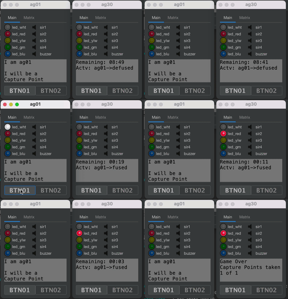
In contrast to static schemes, the agents can also handle dynamic signalling. We can show hours and minutes or a progressing timer running from 0% to 100%.
</figure> The above example shows two agents signalling the same remaining timer. The short remaining time is displayed as a progress bar, the long remaining time is signalled to show the remaining seconds.
Progress
{
  "led_all":"progress:remaining"
}
This message will bind all leds to the “remaining” timer, showing a progressing situation. When the timer has run out, the leds are switched off.
Timer
{
  "led_grn":"timer:remaining"
}
This message will bind the green led to the “remaining” timer. When the timer has run out, the led is switched off. The time will be signalled by a special blink code.
| time of led set to on | stands for |
|---|---|
| 1 second | 1 hour |
| 625 milliseconds | 10 minutes |
| 250 milliseconds | 1 minute |
Smaller time units can not be signalled.
Signal devices
The agent abstracts devices from their GPIO counterparts on the Raspi. The following devices are recognized: led_wht, led_red, led_ylw, led_grn, led_blu, sir1, sir2, sir3, btn01, btn02, buzzer. “sir” stands for siren. So the meaning of this list should be pretty obvious.
There are 3 device groups:
all→ All pins.led_all→led_wht, led_red, led_ylw, led_grn, led_blusir_all→sir1, sir2, sir3
Example:
A signal which causes the agent to buzz two times (75 ms) would have a payload like this:
{"buzzer":"2:on,75;off,75"}
If we want all LEDs to blink every second (until further notice), we would send this:
{"led_all":"infty:on,1000;off,1000"}
or in short:
{"led_all":"normal"}
We can combine multiple payloads into one message. Also for the other commands, not only signals.
{
  "led_all": "infty:on,250;off,2500",
  "sir1": "long"
}
Playing MP3 soundfiles
Topic: /rlg/cmd/<myid>/play
{
  "subpath": "intro",
  "soundfile": "bf3"
}
The subpath is located under the audio folder (see Workspace). The mp3 extension is added to the soundfile. If a soundfile is missing or the player is not installed, this command will be ignored.
Outbound event channel
Events are something that happens to or on the agent. They are reported to the commander.
Buttons
Topic: /rlg/evt/ag01/btn01 or /rlg/evt/ag01/btn02
The use of a button is divided into two separate events:
- The first one reporting that the button is pressed down:
{"button":"down"} - the second one when the button is released again:
{"button":"up"}
Status
Topic: /rlg/evt/ag01/status
Every 60 seconds an agent reports its current status to the commander. Very important to tell, whether all agents are working correctly during a match.
{
  "mqtt-broker": "localhost",
  "netmonitor_cycle": 96,
  "wifi": "PERFECT",
  "mqtt_connect_tries": 1,
  "essid": "!DESKTOP!",
  "last_ping": "16.03.22, 15:06:27",
  "link": "--",
  "freq": "--",
  "ping_max": "0.044",
  "bitrate": "--",
  "version": "1.0.1.387",
  "ap": "!DESKTOP!",
  "txpower": "--",
  "ping_success": "ok",
  "powermgt": "--",
  "ping_loss": "0%",
  "ping_min": "0.044",
  "ping_avg": "0.044",
  "signal": "-30",
  "ping_host": "localhost",
  "timestamp": "2022-03-16T15:06:27.107081+01:00[Europe/Berlin]"
}


